Servo Drives in Robotics: Common Sizing Mistakes and Control Limits




Why servo drives robotics choices become a project risk so quickly
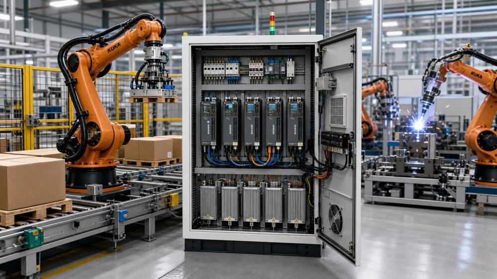
In robotics systems, drive selection shapes accuracy, cycle time, heat, and uptime long before commissioning starts.
That is why servo drives robotics planning cannot be reduced to a catalog torque value.
A packaging robot, a welding cell, and a gantry loader may all use servo drives robotics architectures, yet their limits are not the same.
Some applications live in short burst motion.
Others hold position under constant load.
Some face contamination, unstable power, or long cable runs.
In practical industrial evaluation, the mistake is rarely a single wrong number.
More often, it is a mismatch between motion profile, mechanical inertia, control bandwidth, and operating reality.
For a platform such as Industrial Edge Global, this matters because automation assets are purchased for lifecycle value, not nameplate appeal.
Servo drives robotics decisions affect maintenance exposure, spare strategy, integration complexity, and future line flexibility.
The first useful question is not power, but motion context
Different robotics applications create different sizing pressure.
That pressure comes from acceleration demand, duty cycle, load variation, and positioning tolerance.
A pick-and-place arm often needs high peak torque for very short intervals.
A palletizing axis may need stronger thermal capacity because cycles repeat for hours.
A machine tending robot may appear simple, yet gripper changes can alter inertia more than expected.
That is where many servo drives robotics errors begin.
Teams size for average load, while the drive actually fails at peak acceleration, regeneration, or sustained holding current.
More careful projects separate three questions.
- What torque is needed during the fastest move?
- How long does that torque remain above continuous rating?
- What happens when load, payload, or tooling changes over time?
Those answers usually matter more than a broad motor power category.
Where sizing mistakes show up in real robotic applications
Fast handling cells often get oversized for the wrong reason
High-speed handling lines often push teams toward larger servo drives robotics packages for safety margin.
The logic sounds reasonable, but oversized drives can reduce control quality.
When the drive is too large for the actual inertia range, tuning becomes less forgiving.
Low-load operation may introduce hunting, vibration, or wasted energy.
In these cells, the better approach is checking reflected inertia, acceleration time, and bus utilization together.
Welding and process robots often get undersized thermally
Arc welding, dispensing, and sealing applications may not look aggressive in speed terms.
Still, they can hold difficult positions while compensating for path corrections.
That creates sustained current demand and extra heat inside the drive cabinet.
A servo drives robotics setup that passes peak torque checks may still trip during long shifts.
This is especially common when ambient temperature, enclosure ventilation, and contamination protection were treated separately.
Heavy payload axes fail when inertia and regeneration are ignored
Palletizing, transfer gantries, and vertical lift axes expose another weakness.
The drive may be rated correctly for torque, but not for deceleration energy.
During downward moves or abrupt stops, regenerated energy must go somewhere.
If braking resistors, DC bus sharing, or line regeneration are underspecified, nuisance faults appear under production conditions.
In these installations, servo drives robotics selection should include energy flow, not only motion force.
Different scenarios change what should be checked first
A simple comparison helps show why one sizing method does not fit every robot application.
This is also why Industrial Edge Global frames automation equipment as a long-term production asset.
A drive that fits one robot family may still create avoidable downtime in another production environment.
Control limits are often misunderstood until commissioning
Servo drives robotics performance is constrained by more than rated torque and voltage.
The practical control limit may come from encoder feedback quality, network latency, current loop response, or mechanical resonance.
That becomes visible when a robot meets its speed target but misses repeatability or settling requirements.
A common error is assuming higher gain automatically improves motion.
In reality, unstable mechanics, flexible tooling, or gearbox backlash may define the limit first.
Another issue appears in multi-axis cells.
Servo drives robotics axes can be individually adequate while coordination still fails during interpolation.
That is why checking trajectory smoothness, communication update rates, and synchronized load events is essential before final drive selection.
What gets missed when teams focus only on initial hardware cost
The cheapest acceptable drive on paper may become the most expensive choice across the asset lifecycle.
Servo drives robotics installations are tightly linked to downtime cost, spare parts strategy, and service access.
A drive with limited diagnostics may slow fault isolation.
A platform with weak regional support may extend outage duration.
A model with poor communication compatibility may force expensive controller changes later.
In heavy industry and automated manufacturing alike, these secondary effects influence investment quality as much as motion performance.
This is especially relevant when robotics cells are expected to scale across plants or regions.
- Check whether the same drive family supports future axis expansion.
- Confirm spare availability over the intended machine life.
- Review fault history and tuning tools, not just catalog data.
- Include power quality and cabinet cooling in the cost model.
A more reliable way to match servo drives robotics to the application
Better sizing usually starts with a realistic motion profile, not a generic safety factor.
Capture acceleration, deceleration, dwell time, payload range, and emergency stop conditions.
Then test those values against continuous torque, peak torque duration, and regeneration capacity.
After that, review control-side limits.
Encoder resolution, bus timing, mechanical stiffness, and tuning range should support the required path behavior.
In actual projects, a short checklist improves decisions more than a longer specification sheet.
- Define the worst-case duty cycle, not only nominal production speed.
- Model inertia changes from tooling, workpiece variation, and arm extension.
- Verify thermal behavior inside the intended cabinet and ambient conditions.
- Review braking and energy return under fast stops and vertical motion.
- Confirm serviceability, diagnostics, and communication compatibility.
That process is more aligned with how capital equipment should be evaluated across performance, operating cost, and reliability.
Before final selection, turn assumptions into checks
Servo drives robotics sizing mistakes usually come from assumptions carried too far.
An estimated payload becomes a fixed number.
A short bench test becomes proof of shift-long stability.
A successful single axis becomes evidence for a complete multi-axis design.
The stronger approach is to document the real application window.
List load range, path tolerance, motion frequency, thermal envelope, maintenance constraints, and network architecture.
Then compare candidate servo drives robotics options against those limits, not against marketing claims.
That makes the next decision clearer.
Refine the motion profile, validate control limits early, and measure lifecycle exposure before locking the drive platform.
For complex automation investment, that discipline usually prevents more cost than any late-stage hardware upgrade can recover.
Related News
 What is driving consolidation in the global equipment supplier market?IEG Heavy Machinery & Automation AnalystGlobal equipment supplier market consolidation is accelerating through technology, service, and supply-chain demands. Discover how buyers can capture value while managing risk.
 When does capital equipment investment pay back in manufacturing?IEG Heavy Machinery & Automation AnalystCapital equipment investment manufacturing: learn when equipment truly pays back by evaluating full costs, cash flow, ramp-up, operational risks, and lifecycle value.
 When does a distribution center need an automated pallet handling system?Heavy Lifting Systems AnalystPallet handling systems help distribution centers overcome labor shortages, bottlenecks, safety risks, and storage constraints. Discover the key signs it’s time to automate.
 How to build a machinery investment plan around payback periodIEG Heavy Machinery & Automation AnalystMachinery investment planning manufacturing guide: build a credible payback plan with full costs, ramp-up assumptions, lifecycle risks, and scenario-based cash benefits.
 How to Specify a Modular Packaging Line for Fast Changeovers and Scalable OutputRobotics EngineerModular packaging line specification guide: achieve faster changeovers, scalable output, reliable controls, and lower lifecycle costs with practical planning.
 How industrial IoT devices reduce unplanned downtime in factoriesRobotics EngineerIndustrial IoT devices help factories detect early equipment issues, plan maintenance, and reduce costly unplanned downtime before production is disrupted.
 What is driving industrial machinery market demand in manufacturing?IEG Heavy Machinery & Automation AnalystIndustrial machinery market manufacturing demand is rising as factories pursue automation, energy efficiency, resilient supply chains, and lifecycle productivity gains.
 316L Stainless Steel Pipe Tube Technical Factors That Shape Buyer DecisionsCNC Machining AnalystA technical analysis for 316L stainless steel pipe tube buyers, covering corrosion expectations, pipe route choice, tolerance, surface, and inspection.
 How ground conditions determine crawler piling equipment selectionConstruction Equipment SpecialistCrawler piling equipment selection starts with ground conditions. Learn how soil, rock, groundwater and site constraints shape safer, more productive piling solutions.
 3300mm CNC Beam Saw Sheet Capacity: Layout Checks Before PurchaseCNC Machining AnalystZhongding ZD330 beam saw specifications: assess 3300mm sheet capacity, layout clearances, handling flow, and acceptance checks before buying.
 How Bucket Chain Diamond Dredgers Meet ISO 12100 Safety Requirements in Alluvial Mining ProjectsMining Infrastructure ExpertBucket chain diamond dredger safety made real: how ISO 12100 compliance ensures operator protection, reliability & zero lost-time injuries in alluvial mining.
 Modular Packaging for High-Mix Automotive Assembly Lines: How Standardized Load Units Reduce Line Changeover Time by 37% — Case Study from Tier-1 Supplier in GuangdongHeavy Lifting Systems AnalystModular packaging slashes automotive line changeover time by 37%—discover how standardized load units boost OEE, cut labor costs, and enable seamless high-mix assembly.