Which quality checks matter in lifting technology manufacturing?




Which Quality Checks Matter in Lifting Technology Manufacturing?
In lifting technology manufacturing, quality is not a final-stage activity performed just before shipment. It is a controlled chain that begins with design inputs and purchased materials, continues through fabrication and assembly, and ends only when the machine, its documentation, and its safety functions can be verified against the intended application. A missed weld discontinuity, an incorrect pressure setting, or an untraceable hook can remain invisible until the equipment is carrying a critical load.
For quality control and safety managers, the central question is not simply whether a crane, hoist, lifting beam, winch, or hydraulic lifting system “works” during a brief factory test. The more useful question is whether the manufacturer has demonstrated that the equipment will operate predictably within its rated limits, including foreseeable operating conditions, maintenance activities, and failure scenarios.
That distinction matters because lifting equipment is usually purchased as a long-lived production asset. A buyer must consider load capacity, duty cycle, environment, installation interfaces, operator controls, inspection access, spare parts, and local compliance requirements. Industrial Edge Global (IEG) examines lifting systems in this wider asset context: the technical evidence behind a machine is often as important as the nameplate capacity printed on it.
Start With Design Control and the Rated Capacity Basis
A sound inspection plan starts before any steel is cut. Manufacturers should maintain a clear design basis that identifies the rated capacity, load combinations, operating speeds, duty classification, lifting height, outreach where relevant, environmental assumptions, and expected use of the equipment. These inputs affect structural sizing, rope selection, braking torque, hydraulic settings, motor capacity, and the calibration range of overload protection.
The rated load alone is not enough. Dynamic effects from acceleration, deceleration, slewing, travel, shock loading, wind, or off-centre loading may govern critical components. The quality team should confirm that the design review addresses these conditions rather than treating the lifting mechanism as a static structure. This is especially relevant for mobile cranes, overhead travelling cranes, articulated lifting devices, and systems integrated into automated production lines.
Applicable requirements depend on equipment type and destination market. Examples may include the ASME B30 series in North American contexts, relevant EN standards for particular crane categories, and ISO standards used in design, inspection, or documentation workflows. These references are not interchangeable, and a standard cited in a quotation is not proof of conformity by itself. Quality managers should verify the exact edition, product scope, customer specification, and local legal requirements before releasing the inspection and test plan.
Material Traceability Is a Safety Control, Not a Paper Exercise
The structural load path should be traceable from incoming material to the finished assembly. Depending on the equipment and risk level, this commonly includes plates, profiles, forged hooks, pins, sheaves, rope terminations, chains, fasteners, and load-bearing cast or machined parts. The purpose is practical: if a material issue is found later, the manufacturer must be able to identify affected components and assess the equipment already delivered.
A useful traceability check connects the purchase record, material certificate where specified, receiving inspection, material identification, cutting or machining record, and final component marking. Material mix-ups are most likely when similar-looking grades are stored together, when identification is lost during cutting, or when subcontracted fabrication is not governed by the same documentation discipline.
Receiving inspection should also look beyond certificates. Inspectors need to check dimensions, surface condition, corrosion, deformation, and obvious transport damage. For critical purchased items, confirmation of compatibility matters as well: a hook may be rated appropriately but still be unsuitable for the reeving arrangement, latch design, operating temperature, or intended sling interface.
Weld Quality Requires Process Evidence and Targeted Examination
Welded structures remain one of the highest-risk areas in lifting technology manufacturing. Main girders, booms, frames, pedestal bases, lifting lugs, and bracket assemblies transfer cyclic and sometimes highly concentrated loads. A visually acceptable weld is not automatically a compliant weld, nor does a single non-destructive test result validate an entire production process.
The control framework usually needs approved welding procedures appropriate to the material and joint configuration, qualified welders or operators where required, controlled filler materials, fit-up checks, preheat and interpass-temperature controls when applicable, and inspection records linked to the weld map. A quality plan should identify which joints receive visual testing and where additional methods such as magnetic particle, penetrant, ultrasonic, or radiographic examination are justified by design criticality or contractual requirements.
Inspection timing is often overlooked. Checking fit-up before welding can prevent incomplete penetration, poor root condition, excessive mismatch, and distortion that becomes harder to correct after assembly. Post-weld dimensional checks are equally important. Misalignment in runway interfaces, drum supports, boom sections, wheel locations, or bearing housings can create premature wear and unstable load movement even if each individual weld passes examination.
Safety managers should be cautious when documentation reports only a general statement such as “welds inspected.” The more meaningful evidence states what was inspected, by whom, to which acceptance criteria, at what stage, and how nonconformities were repaired and re-examined.
Mechanical Assembly: Small Errors Can Alter the Load Path
Mechanical assembly checks focus on whether the designed load path has been preserved in the real machine. This includes pin retention, bearing installation, gear mesh, shaft alignment, drum groove condition, rope reeving, sheave rotation, brake clearances, fastener tightening, lubrication points, and guards. The inspection should not stop at presence or appearance. A locking device can be installed but incorrectly engaged; a rope can be reeved in the intended pattern but rub against an edge under travel.
Wire rope and chain systems deserve close attention because their condition directly affects lifting reliability. Checks should cover specification, diameter or size, construction where relevant, end terminations, drum attachment, dead wraps where required by the design, fleet angle, sheave compatibility, and protection from crushing or abrasion. For chain hoists, inspectors should confirm that the chain is not twisted, that the pocket wheel engages correctly, and that the load chain is appropriate for the hoist design.
Fasteners in structural and drive assemblies require a controlled tightening method. Simply recording a torque value may not be sufficient if the specified joint relies on a defined tightening sequence, lubrication condition, angle control, or locking method. Where critical bolted connections are used, the manufacturer should make the assembly method and verification record available to the project quality team.
Hydraulic Systems Need Both Cleanliness and Functional Proof
Hydraulic lifting systems introduce a different set of failure modes: internal leakage, hose damage, pressure drift, uncontrolled lowering, cylinder instability, contamination, and incorrect valve settings. A factory inspection should verify component identification, hose routing, minimum bend radius, protection against chafing, fitting tightness, cylinder mounting, and access to filters and service points.
Cleanliness is not merely an aesthetic issue. Contamination can damage pumps, proportional valves, seals, and precision control elements, causing erratic movement or shortened service life. The appropriate cleanliness target depends on the component supplier’s requirements and the system design. It should be defined rather than assumed. Flushing records, filtration arrangements, fluid identification, and sampling procedures may be relevant on higher-value or more complex systems.
Functional testing should demonstrate smooth lifting and lowering, stable holding, correct pressure relief behaviour, response to control input, and predictable stopping. A cylinder that holds a load briefly in a factory may still require further assessment if there is pressure decay, abnormal temperature rise, noise, vibration, or inconsistent movement through the full stroke.
Controls and Safety Devices Must Be Tested as a System
Modern lifting equipment often combines mechanical systems with variable-frequency drives, programmable controllers, sensors, radio controls, limit switches, load indicators, anti-collision functions, and remote diagnostics. Testing each device separately is necessary, but it does not prove that the overall system is safe. The critical test is the response of the machine when inputs are missing, contradictory, outside their valid range, or affected by a fault.
Key checks commonly include upper and lower travel limits, hoist limit functions, emergency stop behaviour, braking response, overload protection, interlocks, phase or power-loss response, pendant or remote-control integrity, warning devices, and correct direction of motion. Where software participates in a protective function, version control and parameter management become quality issues. An approved program can be undermined by an undocumented field adjustment or an incorrect configuration loaded during commissioning.
Fail-safe design should be examined realistically. If a sensor fails, cable breaks, communication is lost, or power is interrupted, what state does the equipment enter? The expected answer varies by machine and risk assessment, but it should be explicit, tested, and documented. Operators need clear indication of faults rather than ambiguous alarms that encourage bypassing a safety function to keep production moving.
Load Testing Is Essential, but It Is Not the Whole Acceptance Decision
Proof-load and functional tests are among the most visible quality gates in lifting equipment delivery. They can reveal abnormal deflection, brake slip, control instability, interference, unexpected noise, leakage, or structural distress. Yet a passed load test does not replace earlier controls over material, welding, dimensional accuracy, or safety-device settings. It confirms performance under the defined test conditions; it does not automatically demonstrate lifecycle durability under every operating pattern.
The test procedure should identify the load, test configuration, travel path, personnel controls, measurement method, acceptance criteria, and required post-test inspection. The correct test load and method must be established from the applicable standard, product category, contract, and site constraints. Using an arbitrary percentage without confirming the governing requirement can create both compliance and safety problems.
After testing, inspectors should examine the equipment again for permanent deformation, fastener movement, oil leakage, rope damage, abnormal brake wear, and changes in alignment. This is where a disciplined factory acceptance test becomes more than a demonstration for visitors.
Documentation Determines Whether Quality Can Be Sustained in the Field
A lifting system can leave the factory in good condition and still become difficult to operate safely if the handover package is incomplete. Essential records normally include equipment identification, rated capacity information, drawings appropriate to the buyer’s scope, operating and maintenance instructions, inspection and test records, electrical or hydraulic schematics where applicable, spare-parts information, and a clear list of commissioning actions still required at site.
For project owners, the documentation should also make boundaries visible. Does the supplied equipment include runway design, foundations, power supply, installation, operator training, site load testing, or third-party inspection support? Ambiguity at this stage can lead to unsafe assumptions between the manufacturer, installer, and end user.
IEG’s approach to industrial equipment assessment is useful here: evaluate the machine, the evidence trail, and the operating environment together. A technically capable lifting system has limited value if replacement parts cannot be identified, service personnel cannot access key components, or the owner cannot show how critical inspections were completed.
Build the Inspection Plan Around Risk, Not Habit
The strongest quality plans are not the longest ones. They direct attention toward components and processes where failure would have the greatest safety, operational, or commercial consequence. A manually operated workshop hoist, an automated coil-handling crane, and a hydraulic lifting unit for a remote industrial site do not require identical inspection emphasis. Their risks, interfaces, maintenance conditions, and applicable requirements differ.
Before release, quality and safety teams should be able to answer a few practical questions: Is the rated capacity supported by the approved design basis? Are load-bearing materials and welds traceable and adequately inspected? Do brakes, limits, overload functions, and emergency controls respond correctly under realistic test conditions? Is the test evidence tied to the actual machine serial number? Can the site team install, inspect, maintain, and eventually repair the equipment without relying on undocumented knowledge?
Those answers form a more reliable acceptance decision than a polished factory test alone. In lifting technology manufacturing, quality checks matter because they turn design intent into verifiable safety—and give operators, owners, and project teams a defensible basis for putting valuable equipment into service.
Related News
 What is driving consolidation in the global equipment supplier market?IEG Heavy Machinery & Automation AnalystGlobal equipment supplier market consolidation is accelerating through technology, service, and supply-chain demands. Discover how buyers can capture value while managing risk.
 When does capital equipment investment pay back in manufacturing?IEG Heavy Machinery & Automation AnalystCapital equipment investment manufacturing: learn when equipment truly pays back by evaluating full costs, cash flow, ramp-up, operational risks, and lifecycle value.
 When does a distribution center need an automated pallet handling system?Heavy Lifting Systems AnalystPallet handling systems help distribution centers overcome labor shortages, bottlenecks, safety risks, and storage constraints. Discover the key signs it’s time to automate.
 How to build a machinery investment plan around payback periodIEG Heavy Machinery & Automation AnalystMachinery investment planning manufacturing guide: build a credible payback plan with full costs, ramp-up assumptions, lifecycle risks, and scenario-based cash benefits.
 How to Specify a Modular Packaging Line for Fast Changeovers and Scalable OutputRobotics EngineerModular packaging line specification guide: achieve faster changeovers, scalable output, reliable controls, and lower lifecycle costs with practical planning.
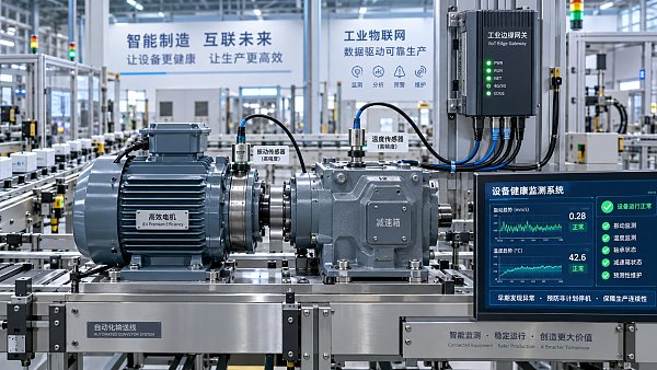
 How industrial IoT devices reduce unplanned downtime in factoriesRobotics EngineerIndustrial IoT devices help factories detect early equipment issues, plan maintenance, and reduce costly unplanned downtime before production is disrupted.
 What is driving industrial machinery market demand in manufacturing?IEG Heavy Machinery & Automation AnalystIndustrial machinery market manufacturing demand is rising as factories pursue automation, energy efficiency, resilient supply chains, and lifecycle productivity gains.
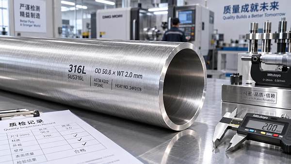
 316L Stainless Steel Pipe Tube Technical Factors That Shape Buyer DecisionsCNC Machining AnalystA technical analysis for 316L stainless steel pipe tube buyers, covering corrosion expectations, pipe route choice, tolerance, surface, and inspection.
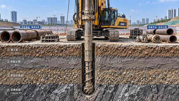
 How ground conditions determine crawler piling equipment selectionConstruction Equipment SpecialistCrawler piling equipment selection starts with ground conditions. Learn how soil, rock, groundwater and site constraints shape safer, more productive piling solutions.
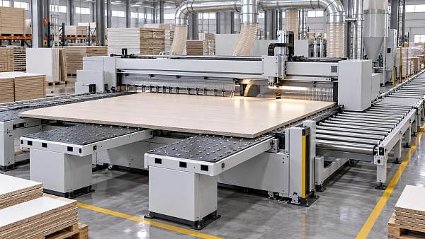
 3300mm CNC Beam Saw Sheet Capacity: Layout Checks Before PurchaseCNC Machining AnalystZhongding ZD330 beam saw specifications: assess 3300mm sheet capacity, layout clearances, handling flow, and acceptance checks before buying.
 How Bucket Chain Diamond Dredgers Meet ISO 12100 Safety Requirements in Alluvial Mining ProjectsMining Infrastructure ExpertBucket chain diamond dredger safety made real: how ISO 12100 compliance ensures operator protection, reliability & zero lost-time injuries in alluvial mining.
 Modular Packaging for High-Mix Automotive Assembly Lines: How Standardized Load Units Reduce Line Changeover Time by 37% — Case Study from Tier-1 Supplier in GuangdongHeavy Lifting Systems AnalystModular packaging slashes automotive line changeover time by 37%—discover how standardized load units boost OEE, cut labor costs, and enable seamless high-mix assembly.