Construction Hoist Safety Inspections: Critical Checks Before Every Shift




A construction hoist should not begin a shift merely because it operated normally the day before. Its safe condition depends on the combined performance of the mast, ties, base, cage, landing interfaces, drive system, electrical controls, and safety devices. A fault in any one area can change loading, stopping distance, travel limits, or access protection. The pre-shift inspection therefore needs to establish that the hoist is correctly assembled, unobstructed, responsive, and able to stop safely under controlled conditions.
The inspection should be performed with the hoist isolated from passenger and material movement until critical items have been examined. Visible defects, unusual sounds, moisture intrusion, missing fasteners, and altered travel paths should be treated as evidence requiring assessment, not as minor site conditions to be ignored. A clean inspection record is useful only when it identifies the actual condition, the location of a defect, the action taken, and the release status of the equipment.
Start with the mast, base, and structural connections
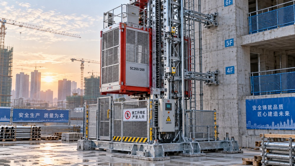
The mast is the primary vertical structure that guides the cage and transfers operating loads to the base and tie system. Inspect mast sections from accessible locations for cracked welds, bent bracing, corrosion that has reduced section integrity, damaged rack teeth, loose bolts, and unauthorized field modifications. Surface dirt alone is not necessarily a structural issue, but packed concrete, hardened mortar, or debris around rack teeth and joints can conceal damage and interfere with cage travel.
Bolted mast joints deserve close attention because a hoist may remain apparently stable while individual fasteners begin to loosen. Look for missing nuts, incomplete engagement, displaced washers, elongated holes, or evidence that adjacent sections are no longer aligned. Fresh rust streaks around a joint, polished contact surfaces, or metal dust near a connection can indicate movement where none should occur. Do not judge a mast joint only by whether every bolt is present; the seating condition and alignment of the joined sections matter as well.
The base frame must sit on its intended support without settlement, distortion, or standing water that could affect the foundation area. Check that the base is free of impact damage and that anchoring points have not loosened. If excavation, vehicle traffic, concrete placement, or drainage work has changed conditions around the base, the previous inspection result no longer represents the current installation.
Tie anchors and wall brackets require the same level of attention as the mast. They restrain the structure against movement caused by load travel, wind, and cage acceleration. Verify that tie components are installed at the required locations, brackets are seated against their support structure, pins and retaining devices are secured, and no element has been bent by collision or used as an improvised attachment point. A tie connected to incomplete, weak, or altered building work can create a false sense of restraint even when the bracket itself appears intact.
Access protection must work as a system
Landing gates, cage gates, enclosure panels, and interlocks prevent exposure to an open shaft or moving cage. Their condition should be assessed as an interconnected system rather than as separate doors. A landing gate that closes but does not latch positively is not equivalent to a secured gate. A cage gate with a damaged latch may affect the electrical interlock circuit, while a bent landing gate can appear closed even though its locking point is not fully engaged.
Open and close each accessible gate through its normal movement. Binding, dragging, excessive free play, missing mesh panels, damaged hinges, and improvised wire or chain restraints require correction. Examine guard panels around the base enclosure for gaps large enough to permit access to moving components. Pay particular attention to corners, gate posts, and areas recently disturbed by material delivery or scaffold changes.
Interlocks should be function-tested through the intended operating sequence. The cage must not travel when a protected gate or door condition is open, and access should remain controlled when the cage is not correctly positioned at a landing. An interlock that works only after a gate is lifted, pushed, or held in a particular position is unreliable. Adjustment may be needed, but adjustment should not be used to compensate for damaged hinges, worn latch components, or deformed frames.
Braking and travel control need dynamic verification
A visual inspection of a motor brake cannot confirm braking performance. Before normal lifting begins, observe the cage response during controlled movement and stopping. The cage should start smoothly, stop without a prolonged coast, and remain stationary when held at a landing. Unusual delay between command release and stopping, harsh grabbing, vibration at stop, or a drift after stopping should remove the hoist from service until the cause is determined.
Brake behavior must be interpreted in context. A sharp stop can arise from brake adjustment, but it can also reflect guide roller problems, rack damage, gearbox irregularity, or cage interference. Similarly, a weak stop may result from worn brake linings, incorrect air gap, oil contamination, electrical release faults, or an issue in the drive control circuit. Repeated button pressing or extended travel tests are not a substitute for investigation when the stopping response changes.
Test normal upper and lower travel limit switches through their designed actuation points. These devices should stop the cage before it reaches an unsafe point in its travel path. Inspect actuators, cams, brackets, and wiring routes for deformation or looseness. A limit switch may function during a hand test yet fail during normal travel if its actuator does not engage consistently at speed.
Final limits and overspeed safety devices require particular care because they are protective devices rather than routine travel controls. Their test method must follow the hoist manufacturer’s instructions and site control procedure. They should never be casually bypassed to continue work, and a device that has activated should be examined before reset. Resetting without identifying why it operated can return a hoist to service with the original fault still present.
Examine the cage, platform, and load path
Inside the cage, inspect the floor, walls, roof, handholds, lighting, control panel, emergency stop, load notice, and gate hardware. The floor should be free of holes, loose plates, accumulated material, oil, and objects that can roll into a gate track or obstruct a pedal or control. Loose pallet boards, projecting reinforcement, and unsecured tools create both falling-object and control-obstruction hazards.
For material hoists or combined passenger-and-material configurations, verify that the platform and enclosure remain suitable for the intended load. The stated rated capacity must not be treated as a simple volume allowance. Load distribution matters because concentrated weight near one side of the cage can affect guide rollers, gate operation, and stopping behavior. Long materials may create a different problem: even when their total weight is acceptable, they can strike landing structures, interfere with gates, or extend beyond protected edges.
Wire ropes and suspension components need evidence-based decisions
Not every construction hoist uses wire ropes as the primary lifting medium; rack-and-pinion units rely on the mast rack and drive pinion for vertical travel. Where wire ropes are fitted for counterweights, platform arrangements, trailing systems, or auxiliary equipment, inspect them according to their actual function. A rope should be examined for broken wires, flattening, kinks, birdcaging, corrosion, crushed areas, damaged terminations, and improper winding on drums or sheaves.
Broken wires should not be assessed only by counting what is visible at one point. Their distribution, the rope construction, the location of damage, and proximity to terminations or sheaves affect the seriousness of the condition. A localized cluster near a termination or a sheave may indicate an underlying alignment or bending problem. Applying lubricant without identifying the source of abrasion can hide the evidence while allowing deterioration to continue.
Sheaves, drum grooves, guards, and anchorage points should be inspected with the rope. A sound rope running over a worn sheave can rapidly become damaged, while a correctly shaped sheave cannot compensate for a rope that has been kinked or improperly reeved. Guards must prevent accidental contact without trapping debris against a moving rope.
Electrical condition is part of mechanical safety
Inspect supply cables, trailing cables, plugs, junction boxes, pendant controls, cable supports, and protective conduits for cuts, crushed insulation, exposed conductors, loose glands, or unsupported cable runs. Cable damage is often concentrated where the route crosses a landing, passes a sharp edge, enters the cage, or moves through a repeated bend zone. Temporary repairs using unsuitable tape, connectors, or unsecured routing should not remain in service.
Open control enclosures only under the applicable isolation procedure. Look for moisture, dust buildup, overheated terminals, discolored components, loose wiring, and signs of arcing. A tripped protective device should not be reset repeatedly without determining whether the cause was overload, a short circuit, ground fault, mechanical drag, or water ingress. The electrical symptom may be the first visible sign of a mechanical issue elsewhere in the hoist.
Confirm that the emergency stop is accessible, clearly identifiable, and functional. Emergency stopping devices are not a replacement for normal stopping controls, so both functions should be verified. Communication devices, alarms, and landing call controls also need attention where fitted, particularly after cable relocation or work near the mast.
Inspection records should preserve the decision trail
A pre-shift record should identify the specific hoist, date, time, inspected areas, defect description, corrective action, and final equipment status. Generic entries such as “all clear” provide little value when a later fault must be traced. A useful record distinguishes between a condition corrected before release, a condition requiring further maintenance, and a condition that requires the hoist to remain out of service.
Photographs, defect tags, and maintenance references can support the record when damage is localized or difficult to describe. They should supplement, rather than replace, a clear written statement of the problem. For example, “mast section joint at upper landing shows loose fastening and visible movement marks” is more actionable than “mast issue.”
Construction hoist safety is maintained through consistent judgment at the start of each shift. A cage that travels, a gate that closes, or a control that energizes does not by itself demonstrate safe operating condition. The equipment should be released only when the structural path, access barriers, stopping functions, travel controls, electrical protection, and load area all remain suitable for the work about to begin.
Related News
 MSHA Issues Mine Truck Safety Alert After One Death and 121 InjuriesMining Infrastructure ExpertMSHA mine truck safety alert reports one death and 121 lost-time injuries. Discover why mine operators should review safety practices.
 How to size a crushing plant for ore processingMining Infrastructure ExpertSize your ore processing equipment crushing plant with confidence. Learn how to calculate throughput, assess ore characteristics, and prevent bottlenecks.
 Trump Administration Rewrites Mining Policy to Spur Critical Minerals DevelopmentMining Infrastructure ExpertU.S. critical minerals mining policy is changing. Explore what faster approvals could mean for investment, equipment demand and supply chains.
 How IEC 62443 defines security zones for industrial communication systemsRobotics EngineerExplore industrial communication systems and IEC 62443: learn how security zones, conduits, and risk-based controls help protect plant operations.
 China-Peru Trade Agreement Upgrade Takes Effect, Easing Machinery CertificationConstruction Equipment SpecialistThe China-Peru trade agreement upgrade simplifies machinery certification. Discover what mutual recognition could mean for exporters entering Peru.
 How do industrial control systems regulate water treatment?Robotics EngineerDiscover how industrial control systems in water treatment use sensors, PLCs, and SCADA to regulate processes and help operators respond to changing conditions.
 Exotec Report: 25% of Supply Chain Leaders Regret Warehouse Automation DecisionsRobotics EngineerWarehouse automation regret affects 25% of surveyed supply chain leaders, according to Exotec. Explore the cost, contract and readiness risks before investing.
 How to set maintenance intervals for mining equipment in AustraliaMining Infrastructure ExpertMining equipment maintenance Australia: Learn how to set service intervals using operating hours, site conditions and equipment data to reduce downtime.
 EY Survey Ranks Complexity as Mining's Top Risk for 2027Mining Infrastructure ExpertMining risk in 2027 is led by complexity, EY's survey finds. Discover how aging mines, declining ore grades and supply chain pressures are reshaping the industry.
 Can asset lifecycle management automation reduce equipment downtime?IEG Heavy Machinery & Automation AnalystDiscover how asset lifecycle management automation can reduce equipment downtime through timely maintenance, faster repairs, and smarter service workflows.
 Caterpillar Q3 2026 Revenue Rises 17% to $20.7 Billion as Both Equipment Segments GrowConstruction Equipment SpecialistCaterpillar Q3 2026 revenue reportedly rose 17% to $20.7 billion. Explore equipment segment growth and what it could mean for procurement planning.
 How to choose a rugged industrial control panel for wet environmentsRobotics EngineerChoose a rugged industrial control panel for wet environments. Compare IP ratings, materials, seals, and condensation control to improve reliability.