What Causes Motion Control Systems to Drift Out of Calibration?




What Causes Motion Control Systems to Drift Out of Calibration?
What causes motion control systems to drift out of calibration over time? Usually, several small mechanical, thermal, electrical, and software-related changes accumulate until positioning performance no longer meets process requirements.
For manufacturers, plant managers, and automation engineers, calibration drift is not merely a maintenance inconvenience. It can increase scrap, slow cycle times, create quality escapes, and shorten the useful life of expensive equipment.
Effective diagnosis requires distinguishing normal repeatability variation from a genuine loss of accuracy. The practical goal is to identify the dominant source, quantify production risk, and restore reliable machine performance.
Why Calibration Drift Creates a Business Risk
Motion control systems coordinate motors, drives, encoders, mechanics, and control software to place tools, products, or robot arms at expected positions during every operating cycle.
When a system drifts, it may still move smoothly and complete its program. However, the actual position can differ from the commanded position by an unacceptable amount.
In packaging, this can cause poor sealing, misaligned labels, or damaged materials. In machining, it may produce dimensional errors, tool wear, and rejected high-value parts.
For robotics, calibration drift can affect pick accuracy, welding paths, dispensing consistency, camera alignment, and safe clearance around fixtures, operators, or neighboring automated equipment.
The financial impact is often indirect at first. Small deviations may be absorbed by process tolerances until yield falls, rework increases, or a customer identifies a recurring defect.
Plant leaders should therefore treat drift as a lifecycle reliability issue. The relevant question is not only whether a machine runs, but whether it consistently produces within specification.
A useful baseline combines positioning accuracy, repeatability, process quality, cycle time, rejected parts, and maintenance history. These measures reveal whether the problem is isolated or systemic.
Mechanical Wear Is Often the First Physical Cause
Mechanical wear is one of the most common answers to what causes motion control systems to drift out of calibration over time, especially in high-cycle or heavily loaded equipment.
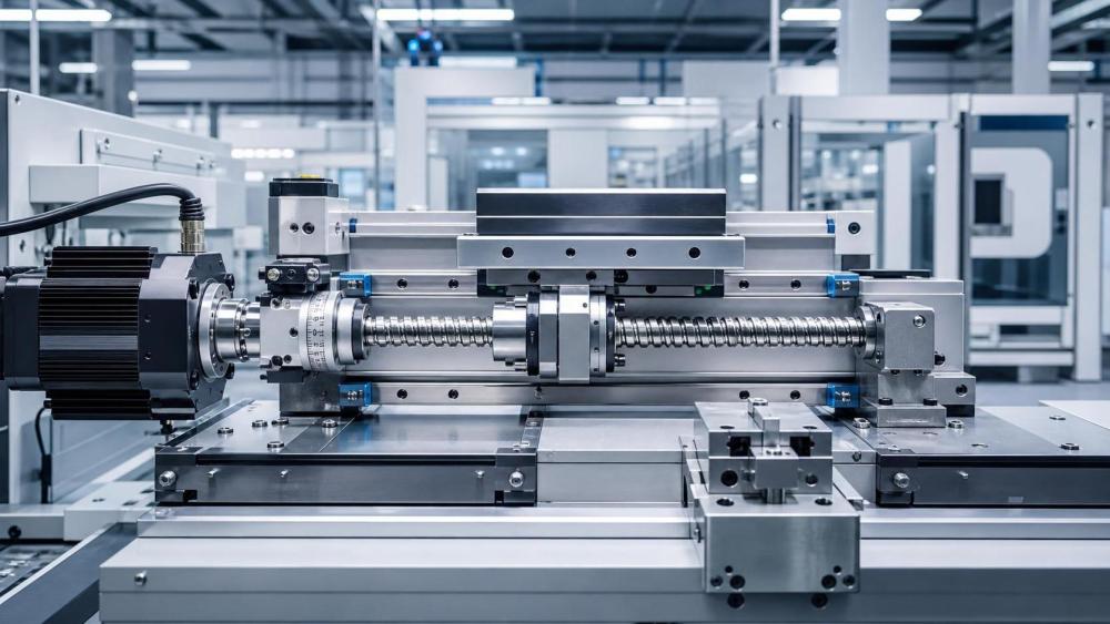
Ball screws, linear guides, gearboxes, belts, couplings, bearings, and rotary tables gradually develop backlash, compliance, friction changes, or uneven resistance during repeated operation.
Even small amounts of backlash can cause an axis to stop differently depending on travel direction. This becomes especially visible during contouring, reversals, and short positioning moves.
Loose couplings can create lost motion between a motor and load. The encoder may report correct motor rotation while the attached mechanism fails to move precisely.
Belt-driven systems can drift when belts stretch, lose tension, wear unevenly, or operate outside their intended load range. Pulley wear may compound the positioning error.
Linear guide contamination can also change axis behavior. Dust, chips, dried lubricant, and corrosion increase friction, creating inconsistent movement that resembles an electrical or tuning problem.
Mechanical inspection should include backlash testing, coupling checks, bearing condition, belt tension, lubrication quality, guide cleanliness, and verification of mounting fasteners under operating load.
Thermal Changes Can Shift Position During Normal Production
Temperature variation is frequently underestimated because a machine may calibrate correctly when cold, then lose accuracy after hours of production at normal operating speed.
Motors, gearboxes, ball screws, hydraulic units, cabinets, and nearby process equipment generate heat. Ambient temperature changes can further alter component dimensions and system behavior.
Steel, aluminum, and other structural materials expand at different rates. Long travel axes are particularly vulnerable because a small dimensional change can become significant across the full stroke.
Ball screws can lengthen as they warm, shifting axis position. Robot arms and machine frames may also deflect differently when motors, weld cells, or surrounding equipment reach stable temperatures.
Thermal effects are not always linear. A rapid production ramp, intermittent duty cycle, or seasonal temperature change can create different drift patterns from one shift to another.
Engineers should compare cold-start results with measurements taken after thermal stabilization. Logging axis temperature, ambient conditions, and positional error helps confirm whether heat is a primary driver.
Where thermal drift is confirmed, solutions may include compensation tables, improved cooling, warm-up routines, insulation, temperature-controlled environments, and redesign of sensitive mechanical structures.
Encoder Errors and Feedback Problems Can Misrepresent Actual Motion
An encoder is the feedback source that tells the controller where a motor or axis is located. If its signal is unreliable, the controller makes decisions using inaccurate information.
Incremental encoders may lose counts because of damaged cables, poor connectors, contamination, electrical interference, or excessive vibration. Absolute encoders can also develop communication or reference issues.
A loose encoder coupling is particularly dangerous because it can produce intermittent errors. The machine may appear accurate during one test and fail during another production sequence.
Optical encoder contamination, damaged scales, worn read heads, and incorrect mounting gaps can reduce signal quality. High-resolution systems may be sensitive to surprisingly minor installation changes.
Feedback errors can also originate away from the encoder itself. Poor grounding, shield termination faults, unsuitable cable routing, and deteriorated connectors may distort position signals.
Diagnostic work should examine encoder alarms, following error trends, signal quality indicators, cable continuity, connector condition, and physical alignment before replacing major drive components.
Replacement parts must match the original resolution, communication protocol, environmental rating, and controller compatibility. An apparently similar encoder can introduce new commissioning and accuracy problems.
Vibration and Shock Gradually Change Mechanical Relationships
Vibration can loosen fasteners, shift sensor brackets, damage bearings, affect connector contact, and change the relationship between a motion axis and its calibrated reference position.
Sources may include presses, compressors, stamping equipment, forklifts, conveyors, unbalanced motors, nearby machining centers, or inadequate foundations beneath precision automation equipment.
Repeated shock loads are especially problematic for robotic end effectors, machine vision components, precision fixtures, and sensors mounted on lightweight brackets or long unsupported structures.
A system may pass a static calibration check while still failing dynamically. Vibration changes the machine behavior during acceleration, deceleration, cutting, handling, or high-speed product transfer.
Inspect for loose mounting bolts, cracked brackets, frame movement, worn isolators, damaged cable carriers, and changes in equipment level. These faults frequently coexist with apparent control issues.
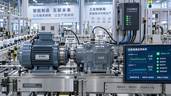
Condition monitoring can help identify vibration-related risk before quality deteriorates. Accelerometers, motor current trends, bearing monitoring, and regular fastener inspections support preventive maintenance programs.
When vibration is unavoidable, isolate the source, strengthen mounting structures, improve foundation design, use suitable cable restraint, and confirm calibration under realistic operating conditions.
Electrical Noise and Power Quality Can Produce Intermittent Drift
Electrical noise does not always create a clear fault code. It can produce sporadic feedback errors, unstable communication, unexpected resets, or subtle position deviations that are difficult to reproduce.
Variable frequency drives, welding systems, contactors, large motors, and poorly filtered switching devices can introduce electromagnetic interference into motion control wiring and sensitive feedback circuits.
Incorrect cable routing is a common installation problem. Encoder and communication cables should be separated from high-power conductors, especially where long runs share trays or conduits.
Ground loops can create voltage differences between connected devices. Improper shielding practices may allow noise into signal paths instead of directing interference safely to ground.
Voltage dips, phase imbalance, poor power factor conditions, and inadequate power supplies can affect servo drives and controllers. These conditions may appear only during peak production demand.
Maintenance teams should review grounding architecture, shielding terminations, cabinet bonding, cable routing, power quality logs, and drive event histories when errors occur unpredictably.
Electrical corrections should follow equipment manufacturer guidance. Randomly changing grounding points or shield connections can worsen interference, create safety concerns, and make later diagnosis more difficult.
Control Parameters and Software Changes Can Shift Performance
Not every calibration problem is caused by physical deterioration. Changes to controller parameters, drive tuning, firmware, motion profiles, or coordinate systems can alter positioning performance immediately.
Servo tuning determines how the system responds to commands and disturbances. Gains that are too low may create lag, while excessive gains can cause oscillation, overshoot, and mechanical stress.
Changes in payload, tooling, product mass, cable routing, or end-of-arm equipment can make previous tuning values unsuitable. This is common after process upgrades or fixture modifications.
Coordinate transformations require careful management in multi-axis machines and robots. Incorrect tool offsets, work offsets, homing settings, or reference frames can look like physical calibration drift.
Software updates may change default parameters, communication timing, diagnostic behavior, or motion functions. Plants should preserve validated backups before any controller, drive, or robot software change.
Configuration control is essential. Record who changed parameters, why the change was made, which machine version applies, and whether accuracy was verified after commissioning.
A disciplined comparison against a known-good backup can quickly identify unauthorized or accidental modifications. It also avoids replacing hardware when the real issue is a changed setting.
Maintenance Gaps Allow Small Problems to Become Accuracy Failures
Inadequate maintenance rarely causes a single dramatic drift event. More often, missed inspections allow lubrication problems, contamination, loose hardware, and damaged cables to accumulate gradually.
Lubrication intervals should reflect duty cycle, contamination exposure, temperature, load, and manufacturer recommendations. Under-lubrication increases friction, while unsuitable grease can damage precision components.
Calibration checks should not be scheduled only after a quality failure. Their frequency should be based on process tolerance, asset criticality, cycle count, historical stability, and cost of downtime.
Critical equipment may require daily verification using production references, while less sensitive machinery may need monthly, quarterly, or annual measurement with traceable calibration instruments.
Maintenance records should capture measured error, correction performed, replacement parts, operating hours, environmental conditions, and recurring observations. This turns isolated repairs into useful reliability data.
Trend analysis helps distinguish normal aging from accelerating deterioration. A stable error can be managed through planned recalibration, while rapidly changing results indicate a developing component failure.
For capital-intensive equipment, preventive calibration is usually less costly than unplanned correction. It protects throughput, reduces scrap exposure, and supports more predictable maintenance labor and spare-parts planning.
How to Diagnose Drift Without Wasting Maintenance Time
Start by defining the symptom precisely. Determine whether the error affects one axis, one direction, one product, one temperature condition, one speed range, or every operating cycle.
Separate accuracy from repeatability. A machine can repeatedly stop at the wrong position, suggesting offset or compensation issues, or stop inconsistently, suggesting wear, friction, noise, or feedback faults.
Review recent changes before disassembling equipment. New tooling, software updates, collisions, maintenance work, environmental changes, and production schedule changes often provide the fastest diagnostic clue.
Measure performance with an appropriate reference. Depending on the application, this may include laser interferometry, dial indicators, ballbar testing, robot calibration tools, vision targets, or precision fixtures.
Test at cold start and after normal operating temperature is reached. Compare results across travel directions, speeds, payloads, and positions to identify thermal, backlash, or dynamic behavior.
Check mechanical condition and electrical integrity before applying software compensation. Compensation can hide a developing failure, leaving the plant exposed to a larger outage later.
After repair or recalibration, validate the actual production process. Axis accuracy alone is insufficient when final quality depends on tooling, fixturing, material behavior, vision systems, or operator setup.
Building a More Reliable Calibration Strategy
The most effective strategy combines design choices, preventive maintenance, measurement discipline, and operational controls. Calibration should be treated as part of asset management, not a last-minute repair activity.
Specify equipment according to the required process tolerance rather than nominal motion capability. A system operating near its accuracy limit will demand more frequent verification and tighter environmental control.
During procurement, assess encoder quality, environmental protection, mechanical stiffness, service accessibility, diagnostic functions, spare-parts availability, and supplier support for calibration and commissioning.
Standardize acceptance testing when new equipment is installed. Document baseline accuracy, repeatability, thermal behavior, controller versions, tuning values, and measurement methods before production begins.
Use alarms and condition data to trigger inspections where possible. Following error, drive temperature, vibration, motor current, cycle count, and encoder diagnostics can identify developing issues earlier.
Train operators to report subtle changes, such as abnormal noise, slower motion, repeated homing, inconsistent product alignment, or a growing need for manual adjustment during setup.
Most importantly, link calibration performance to operational outcomes. When accuracy data is connected to scrap, downtime, throughput, and customer quality risk, maintenance priorities become easier to justify.
Conclusion: Treat Drift as a Manageable Lifecycle Issue
What causes motion control systems to drift out of calibration over time is rarely a mystery once mechanical condition, temperature, feedback integrity, electrical environment, software changes, and maintenance history are examined together.
Mechanical wear and thermal expansion are frequent causes, but encoder faults, vibration, electrical interference, and configuration changes can produce similar symptoms and require different corrective actions.
The strongest response is systematic diagnosis rather than repeated adjustment. Measure the error, identify the operating conditions that trigger it, correct the root cause, and validate process performance.
For industrial decision-makers, a structured calibration program protects more than motion accuracy. It preserves product quality, equipment availability, maintenance budgets, customer confidence, and the lifecycle value of automation investments.
Related News
 What is driving consolidation in the global equipment supplier market?IEG Heavy Machinery & Automation AnalystGlobal equipment supplier market consolidation is accelerating through technology, service, and supply-chain demands. Discover how buyers can capture value while managing risk.
 When does capital equipment investment pay back in manufacturing?IEG Heavy Machinery & Automation AnalystCapital equipment investment manufacturing: learn when equipment truly pays back by evaluating full costs, cash flow, ramp-up, operational risks, and lifecycle value.
 When does a distribution center need an automated pallet handling system?Heavy Lifting Systems AnalystPallet handling systems help distribution centers overcome labor shortages, bottlenecks, safety risks, and storage constraints. Discover the key signs it’s time to automate.
 How to build a machinery investment plan around payback periodIEG Heavy Machinery & Automation AnalystMachinery investment planning manufacturing guide: build a credible payback plan with full costs, ramp-up assumptions, lifecycle risks, and scenario-based cash benefits.
 How to Specify a Modular Packaging Line for Fast Changeovers and Scalable OutputRobotics EngineerModular packaging line specification guide: achieve faster changeovers, scalable output, reliable controls, and lower lifecycle costs with practical planning.
 How industrial IoT devices reduce unplanned downtime in factoriesRobotics EngineerIndustrial IoT devices help factories detect early equipment issues, plan maintenance, and reduce costly unplanned downtime before production is disrupted.
 What is driving industrial machinery market demand in manufacturing?IEG Heavy Machinery & Automation AnalystIndustrial machinery market manufacturing demand is rising as factories pursue automation, energy efficiency, resilient supply chains, and lifecycle productivity gains.
 316L Stainless Steel Pipe Tube Technical Factors That Shape Buyer DecisionsCNC Machining AnalystA technical analysis for 316L stainless steel pipe tube buyers, covering corrosion expectations, pipe route choice, tolerance, surface, and inspection.
 How ground conditions determine crawler piling equipment selectionConstruction Equipment SpecialistCrawler piling equipment selection starts with ground conditions. Learn how soil, rock, groundwater and site constraints shape safer, more productive piling solutions.
 3300mm CNC Beam Saw Sheet Capacity: Layout Checks Before PurchaseCNC Machining AnalystZhongding ZD330 beam saw specifications: assess 3300mm sheet capacity, layout clearances, handling flow, and acceptance checks before buying.
 How Bucket Chain Diamond Dredgers Meet ISO 12100 Safety Requirements in Alluvial Mining ProjectsMining Infrastructure ExpertBucket chain diamond dredger safety made real: how ISO 12100 compliance ensures operator protection, reliability & zero lost-time injuries in alluvial mining.
 Modular Packaging for High-Mix Automotive Assembly Lines: How Standardized Load Units Reduce Line Changeover Time by 37% — Case Study from Tier-1 Supplier in GuangdongHeavy Lifting Systems AnalystModular packaging slashes automotive line changeover time by 37%—discover how standardized load units boost OEE, cut labor costs, and enable seamless high-mix assembly.