How mine ventilation systems control dust at the source




Dust control is most effective when the ventilation system captures contaminated air before it enters the wider mine atmosphere. Once fine particles leave a drill collar, crusher inlet, loading point, or conveyor transfer, they are carried by vehicle movement, pressure changes, and recirculating airflow. Dilution then requires much larger air volumes and still leaves areas where respirable dust can remain concentrated. Source control therefore starts with identifying the release point, enclosing it as far as the process permits, and creating a deliberate airflow path toward a collection or exhaust point.
A mine ventilation system controls dust at the source through a combination of local exhaust, directional airflow, enclosure, filtration, and process coordination. The system must move enough air to overcome the dust plume's momentum and nearby cross-currents, while avoiding air velocities that pick up settled material from floors, roadways, and ledges. Effective design is not simply a matter of installing a larger fan. Air quantity, hood location, duct condition, equipment motion, material moisture, and the sequence of mining activity all affect whether dust is captured or released.
Capture the plume where it forms
At a fixed or semi-fixed source, local exhaust ventilation is usually the first engineering control to assess. A hood, shroud, drill canopy, sealed housing, or ducted enclosure is positioned close enough to the release zone that airborne material is drawn into the system before workers nearby are exposed. The more open the source, the more difficult this becomes. A fully enclosed crusher feed chute requires less capture airflow than an open tipping point where a loader discharges fragmented rock from height.
The critical measurement is not fan capacity stated on a datasheet; it is the air movement achieved at the source under operating conditions. A fan may produce a high volume in free air yet deliver weak capture at the hood because of duct friction, poor joints, crushed flexible duct, blocked filters, or an incorrect damper position. Long duct runs, abrupt elbows, rough internal surfaces, and undersized branches increase resistance. Leakage upstream of the hood can be equally damaging because the fan draws cleaner air through gaps instead of contaminated air from the intended capture zone.
Drilling illustrates the difference between nominal and effective capture. Dust is released at the hole collar, but the drill steel, feed movement, broken ground profile, and machine positioning continuously alter the opening around the collar. A collection system that performs well on level, competent ground may lose control where fractured material prevents the shroud from seating. Dry drilling produces a different plume from wet drilling, and high-pressure air used to clear cuttings can overwhelm a weakly designed collector. The correct response is not automatically to increase airflow: excessive suction can interfere with water delivery, pull fines past poorly sealed access points, or create unwanted turbulence around the work area.
Use airflow direction as a containment tool
General mine ventilation provides the larger airflow framework into which local capture systems must fit. Intake air should reach occupied work areas before it passes significant dust sources. Exhaust air should carry contaminants away without sweeping the plume across personnel, adjacent headings, maintenance bays, or fresh-air routes. Where a production face includes drilling, loading, and haulage, the order and location of these activities can change the ventilation result as much as a duct adjustment.
Pressure relationships matter. An enclosure works best when air is drawn inward through its openings rather than pushed outward with dust-laden air. This is why a crusher house, bagging station, or transfer tower is often arranged under slight negative pressure. However, excessive negative pressure can make doors hard to use, pull dust from another uncontrolled opening, and increase the amount of outside air that must be filtered or exhausted. The objective is stable inward flow at openings that cannot be sealed, not the greatest possible pressure difference.
Underground, auxiliary fans and ventilation ducting direct fresh air toward active headings and remove contaminated air from the working zone. The duct outlet has to be placed with the actual task in mind. A discharge point that is too far from a development face allows dust to linger; one that is too close or aimed directly at broken material may stir deposits and disturb the dust cloud. Changes in tunnel geometry, a partially obstructed airway, a new crosscut, or mobile equipment parked near the face can all alter flow patterns. Smoke-tube observations or equivalent airflow visualization during normal production often reveal short-circuiting and dead zones that are not obvious from a ventilation plan alone.
Different sources need different control arrangements
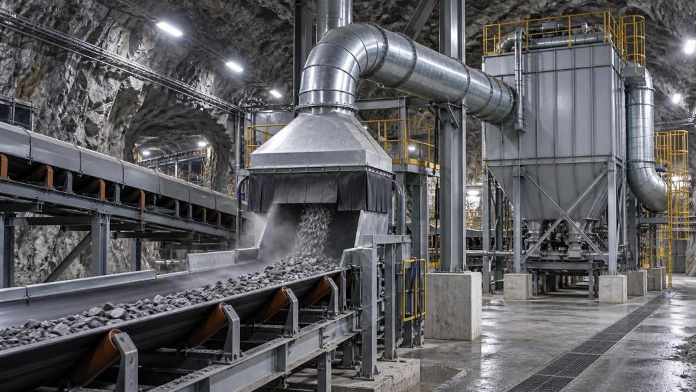
Dust sources can look similar while requiring different control methods. Fine dry material released from a conveyor belt transfers readily into an enclosure and exhaust hood. Dust generated by a falling rock stream has greater momentum and may escape unless the chute geometry slows the material before it reaches the opening. A loader dumping into a hopper generates displacement air: the incoming rock forces dusty air out of the hopper, even when the falling stream itself appears contained. At that location, baffles, partial enclosures, reduced drop height, and a dedicated exhaust path often matter more than adding a spray bar alone.
Water suppression is often paired with ventilation, but it should be treated as a source-conditioning measure rather than a replacement for capture. Properly applied water binds fine particles to coarser material before they become airborne. Poorly aimed sprays can create wet surfaces while leaving the airborne plume unchanged. Excess water may block chutes, cause belt carryback, complicate downstream processing, or increase slip hazards. Material that is already damp may need little additional water, while hydrophobic or very fine material may require different nozzle placement, droplet size, or a surfactant program approved for the process.
Enclosure quality determines whether extraction works
Local exhaust systems frequently underperform because the physical containment around the source has degraded. Torn rubber curtains, warped access panels, missing covers, damaged skirt boards, and gaps around conveyor penetrations give dust an easy exit. They also increase the air volume required to maintain inward flow. Repairing these defects can improve capture more effectively than replacing an existing fan with a larger unit.
Access is a practical design constraint. A housing that cannot be opened quickly for clearing a blockage or replacing wear components will eventually be left open, removed, or modified in the field. Covers and doors need durable latches, visible closed positions, and seals that tolerate abrasion and repeated handling. Inspection windows should be positioned where material flow can be observed without opening the enclosure. In high-wear areas, liners and flexible seals should be considered consumable components with defined inspection intervals rather than permanent fittings.
Make-up air also deserves attention. Extracting air from an enclosed transfer point without a planned replacement path can cause air to enter through the least desirable opening. This may pull dust across an access door or draw contaminated air from a neighboring process. A controlled make-up opening on the clean side of the enclosure establishes the direction of travel: clean air enters, passes across the release point, and exits through the extraction duct. The path should be checked while the equipment is loaded, because an empty conveyor or idle crusher does not produce the same air displacement or dust behavior.
Filtration and ductwork are part of the control point
Collected air must remain contained until it reaches a suitable discharge or filtration device. Dust collectors, cartridge filters, bag filters, cyclonic pre-separators, scrubbers, and other devices are selected according to particle characteristics, moisture, temperature, abrasiveness, and required air volume. Fine, dry, free-flowing dust behaves differently from sticky clay-bearing fines or fibrous material. A filter suitable for one may blind quickly when exposed to the other.
Pressure drop across a collector is useful only when interpreted with operating context. A rising differential pressure can indicate loaded media, but it may also reflect a failed cleaning cycle, wet dust, a blocked hopper, or an incorrect sensor connection. A low reading is not automatically good news; it can result from damaged filter media, a leak, an open bypass, or insufficient airflow. The collector's discharge arrangement also matters. If accumulated dust cannot leave the hopper consistently, it may build back into the filter area, impair cleaning, and re-enter the air stream.
Duct inspection should focus on details that change flow: flexible sections flattened by traffic, joints that have separated, abrasion holes near bends, unsupported sections that sag, and deposits that reduce internal area. Abrasive mine dust commonly attacks elbows and transition pieces first. A duct that appears intact from a distance may leak significantly at a worn elbow or failed clamp. Maintenance records are more useful when they distinguish the location and nature of the defect rather than recording only that “ventilation was serviced.”
Monitoring must confirm exposure control, not just equipment operation
Fan status, duct pressure, filter differential pressure, and airflow indicators show whether components are running within an expected range. They do not by themselves prove that dust is controlled at the source. A running fan can coexist with an ineffective hood; a normal pressure reading can coexist with a changed work sequence that directs dust into a travelway.
A strong verification routine combines three perspectives. Visual inspection identifies escaped plumes, dust deposits around enclosure joints, and damaged barriers. Airflow checks confirm that movement is toward the capture point and that duct delivery has not fallen away from the design condition. Personal and area dust monitoring then tests whether the system is controlling the respirable fraction in the places where exposure occurs. These observations should be reviewed together. A clean-looking process may still produce fine particles that are difficult to see, while visible coarse dust may be a containment issue without being the dominant respirable fraction.
Trend changes deserve investigation even when readings remain within internal action levels. A gradual increase near one transfer point can indicate seal wear, altered belt loading, a clogged spray nozzle, or ventilation being diverted by a new opening. Sudden changes often point to a mechanical event: a fan trip, collapsed duct, broken door latch, failed filter-cleaning system, or an enclosure left open after maintenance. Linking monitoring records to maintenance work orders, production rate changes, and ventilation adjustments makes the cause easier to isolate.
Commission under realistic operating conditions
Commissioning should occur while the source is producing its expected material flow, not only when equipment is empty and clean. Observe a full loading cycle, the highest practical feed condition, normal vehicle movements, and any process state that opens access doors or changes hood geometry. Record airflow direction at relevant openings, visible leakage points, collector condition, and the position of dampers or regulators. These baseline details make later troubleshooting faster because they show what “normal” looked like when the system was functioning properly.
When a dust-control problem persists, start at the source and follow the intended air path outward: release point, enclosure openings, hood position, duct continuity, fan operation, collector condition, and discharge. This order prevents a common error of treating the collector as the cause when the real failure is an open panel or changed process geometry upstream. Dust control remains stable when ventilation, containment, and the mining process are maintained as one operating system rather than as separate pieces of equipment.
Related News
 What is driving consolidation in the global equipment supplier market?IEG Heavy Machinery & Automation AnalystGlobal equipment supplier market consolidation is accelerating through technology, service, and supply-chain demands. Discover how buyers can capture value while managing risk.
 When does capital equipment investment pay back in manufacturing?IEG Heavy Machinery & Automation AnalystCapital equipment investment manufacturing: learn when equipment truly pays back by evaluating full costs, cash flow, ramp-up, operational risks, and lifecycle value.
 When does a distribution center need an automated pallet handling system?Heavy Lifting Systems AnalystPallet handling systems help distribution centers overcome labor shortages, bottlenecks, safety risks, and storage constraints. Discover the key signs it’s time to automate.
 How to build a machinery investment plan around payback periodIEG Heavy Machinery & Automation AnalystMachinery investment planning manufacturing guide: build a credible payback plan with full costs, ramp-up assumptions, lifecycle risks, and scenario-based cash benefits.
 How to Specify a Modular Packaging Line for Fast Changeovers and Scalable OutputRobotics EngineerModular packaging line specification guide: achieve faster changeovers, scalable output, reliable controls, and lower lifecycle costs with practical planning.
 How industrial IoT devices reduce unplanned downtime in factoriesRobotics EngineerIndustrial IoT devices help factories detect early equipment issues, plan maintenance, and reduce costly unplanned downtime before production is disrupted.
 What is driving industrial machinery market demand in manufacturing?IEG Heavy Machinery & Automation AnalystIndustrial machinery market manufacturing demand is rising as factories pursue automation, energy efficiency, resilient supply chains, and lifecycle productivity gains.
 316L Stainless Steel Pipe Tube Technical Factors That Shape Buyer DecisionsCNC Machining AnalystA technical analysis for 316L stainless steel pipe tube buyers, covering corrosion expectations, pipe route choice, tolerance, surface, and inspection.
 How ground conditions determine crawler piling equipment selectionConstruction Equipment SpecialistCrawler piling equipment selection starts with ground conditions. Learn how soil, rock, groundwater and site constraints shape safer, more productive piling solutions.
 3300mm CNC Beam Saw Sheet Capacity: Layout Checks Before PurchaseCNC Machining AnalystZhongding ZD330 beam saw specifications: assess 3300mm sheet capacity, layout clearances, handling flow, and acceptance checks before buying.
 How Bucket Chain Diamond Dredgers Meet ISO 12100 Safety Requirements in Alluvial Mining ProjectsMining Infrastructure ExpertBucket chain diamond dredger safety made real: how ISO 12100 compliance ensures operator protection, reliability & zero lost-time injuries in alluvial mining.
 Modular Packaging for High-Mix Automotive Assembly Lines: How Standardized Load Units Reduce Line Changeover Time by 37% — Case Study from Tier-1 Supplier in GuangdongHeavy Lifting Systems AnalystModular packaging slashes automotive line changeover time by 37%—discover how standardized load units boost OEE, cut labor costs, and enable seamless high-mix assembly.